Special Considerations When Using
Kino Flo Image 85s
on Studio Electrical Systems
Large stage bound productions can involve techniques and equipment that can have an adverse effect on the quality of power within a stage’s electrical distribution system. For instance, much of today’s lighting technology relies on electronics such as DC rectifiers, silicone-controlled rectifiers, capacitors, and high-frequency switching power supplies. The harmonic currents generated by these kinds of load can have undesirable effects on the current waveform, revealing themselves in the form of overheating or failing equipment, efficiency losses, circuit breaker trips, excessive current on the neutral wire, interference and instability with generators, noisy or overheating transformers and service equipment, and even loosened electrical connections.
The severity of these adverse effects can vary depending on whether power is being provided by the house or supplemented by diesel generators. In order to safely distribute electricity throughout a stage, electricians need to understand the origin of harmonic currents, their effect on equipment Power Factor, how they interact with a system’s impedance, and the inherent limitations of a stage’s service equipment in handling them. An awareness of these effects is the first step towards developing successful strategies for eliminating or mitigating the adverse effects of harmonic currents.
In the following paper, we discuss the electrical characteristics of one type of stage lighting fixture, the Kino Flo Image 85, and look how the use of them in large quantities can have an adverse effect on the power quality of a
stage. An awareness of these effects will help us to build distribution systems that avoid or mitigate problems on our stage rigs.

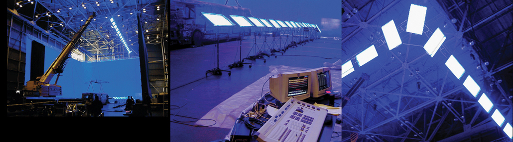
Image 85 fluorescent light fixtures are commonly used by the hundreds to light Chroma Key and Ultimatte stages because they offer many benefits in this application. Effects stages need to be lit evenly and with the best possible color saturation. Evenness is easily achieved using Kino Flo Image 85s because of the soft quality of the light and the wide beam spread. In effects work, it’s not as much about how much light is used to light a stage, but rather what produces the best saturation of reflected blue or green light. For film or high end HD shooting the best saturation of color is achieved by using Kino Flo’s 420nm blue-spike lamps on
blue screens and 525nm green-spike lamps on green screens. Finally the use of Image 85 fixtures offer tremendous energy savings as well.

Capable of ten times more light per watt than tungsten lighting, fluorescent light sources like the Image 85 offer tremendous energy savings. Not only do the lights consume less power, but they also generate less heat, which results in energy savings in the amount of air conditioning required to keep the stage comfortable.
They also offer both energy and cost savings because the color specific spike tubes for both green screen and blue screen applications mentioned above eliminate the cost of gels to reach the desired color saturation - the energy savings comes in not having to
go to a larger fixture to compensate for the loss of output that results from putting gels on the fixtures in order to obtain the desired color saturation.
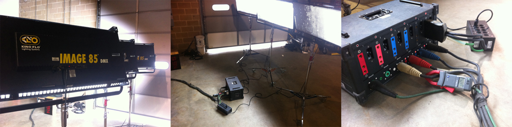
When lighting blue or green screens, Image 85 fixtures are usually rigged in rows with fixtures placed 7ft (2m) on center. Typically there is a row at the top and bottom of a screen in order to make the reflected light more even over the screen and to increase brightness of
the blue or green reflected light. As pictured above, 18 Image 85 fixtures are typically required to light a 40x40 backdrop. Which means that upwards of 175 Image 85s are required to light the 390 linear feet of a 3 wall temporary cyc (120+120+150=390) of
a 120’ x 150’ stage.

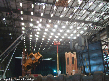
And, if in addition to lighting the cyc walls, Image 85s are used for overall top illumination (as seen is some of these production stills) an additional 180 Image 85 fixtures may be used. The problem from an electrical distribution standpoint is that Image 85s
exhibit electrical characteristics that must be taken into consideration when used in this quantity.
The electrical characteristics of the Image 85 fixture that should be taken into consideration are many. An Image 85 is a fluorescent light fixture that uses qty eight 75W T-12 fluorescent tubes for a total of 600W per light. But, because the
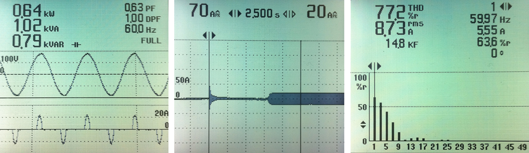
ballasts in the Image 85 head are non-power factor corrected Switch Mode Power Supplies with large smoothing capacitors, the Image 85 has a Power Factor (PF) of .64, which means that each head has an Apparent Power of 938VA for it’s 600W output. While its RMS load is
nominally 8.4A, its peak load is 20A with a crest factor of about 2.25. Started cold, it has an inrush current of 70A peak for a period of about 24 cycles while its smoothing capacitors charge. And, finally it is harmonically rich with a Total Harmonic Distortion (THD) of 77%.
Before looking at the effect on the electrical service head of a stage of using this non-linear load in the quantities pictured in the production stills above, let’s first look at the effect on just one of a stage's individual company switches.
Current on System Neutrals:
As can be seen in the Power Quality Meter reading of a single Image 85 fixture below, with a THD of 77%, Image 85 heads generate a lot of harmonic currents. The distribution of harmonic currents generated by a single fixture is as follows:
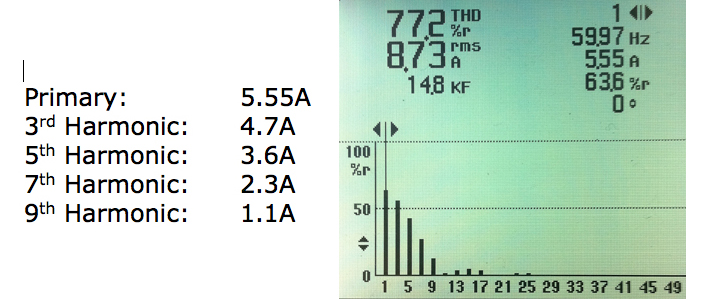
The high content of the 3rd and 9th Harmonics are of particular concern when using these fixtures by the hundreds on stages because the 3rd harmonic, and odd multiples of the 3rd (9th, 15th, etc - called the triplen harmonics) can lead to unusually high current levels on the system neutral,
which is a potential fire hazard and can cause the neutral conductor and connectors to deteriorate or fail catastrophically. Here's why: AC power is delivered throughout the distribution system at a fundamental frequency of 60 Hz. (50 Hz in Europe.)
The harmonic currents generated by Image 85 fixtures are integral multiples of this fundamental frequency. For instance, the 3rd harmonic frequency is 180 Hz, the 5th is 300 Hz, etc. In the US, the standard configuration of service transformers providing
power to motion picture stages is delta-to-wye.

Hence there are three phase wires and a neutral wire on the secondary or load side of the service transformer. The voltage between any two phase wires is 208, and the voltage between any single phase wire and the neutral wire is 120. All 120 volt loads, including
Image 85s, are connected between a phase and neutral. When the loads on all three phases are balanced (the same fundamental current is flowing in each phase), the fundamental currents returned to the neutral cancel and the neutral wire carries no current.
Phase cancellation of the fundementals currents generated by incandescent lamps (a linear load) is illustrated below.

When the loads are non-linear (Image 85s in this case) the situation changes. Since the front end components of an Image 85 ballast uses smoothing capacitors to flattened out rectified AC current, they draw current in spikes and generate harmonic currents. As can be seen on the power quality meter screen above, the largest harmonic current generated is the 3rd. Also generated, in smaller amounts, are the 5th, 7th, and all other
odd harmonic currents. Like the fundamental currents, most harmonic currents cancel out on the neutral wire. The triplen harmonics (the 3rd, 9th, 15th, etc) however are troublesome when dumped back into the neutral of the distribution system.

The reason triplen harmonics are troublsome is that, as can be seen in the illustration above, they are
in phase with each other. For this reason, rather than cancel each other out on the neutral conductor, as the out of phase fundamentals normally do, they instead add up (as illustrated below.)

By generating harmonic currents that stack one upon another, and shifting the phase angle of the primary currents so that they don't entirely cancel, the non-linear electronic ballasts of Image 85 heads can create unusually high returns on the neutral of the distribution system.
For example, if each phase wire were carrying, in addition to fundamental current, 100 amps of 3rd harmonic current, the neutral wire could be carrying 300 amps of 3rd harmonic current. This extra current provides no useful power to the loads. It simply reduces the capacity of the system to power more loads, and produces waste heat in all the wiring and switchgear. When the 3rd harmonic current returns to the transformer it is reflected into the transformer primary where it circulates in the delta winding until it is dissipated as heat. The result is overheated neutral wires, switchgear, and transformers. This can lead to failure of some part of the distribution system and, in the worst case, fires.
To determine the magnitude of the current one might expect on a switch neutral from an effects production using hundreds of Image 85 fixtures, we conducted the following test: we metered the power drawn by an Image 85 on each phase of a 3-phase distribution
system and the current returning on the system neutral. The results are pictured below:
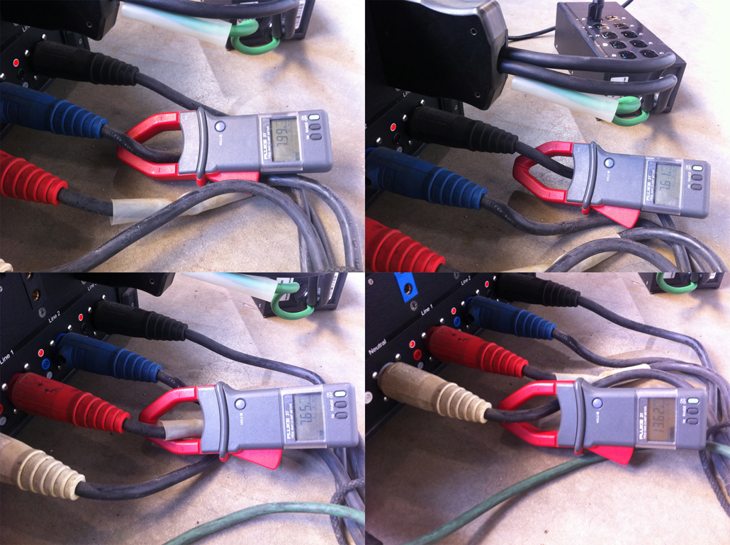
A neutral current of 13.62 when the average of the phase currents is only 7.77A clearly shows that the triplen harmonics generated by the Image 85 fixtures are accumulating on the neutral, rather than cancelling each other out as the out of phase fundamentals normally do.
In fact, the neutral is carrying 176% of the average load on the individual fundamental phase legs.
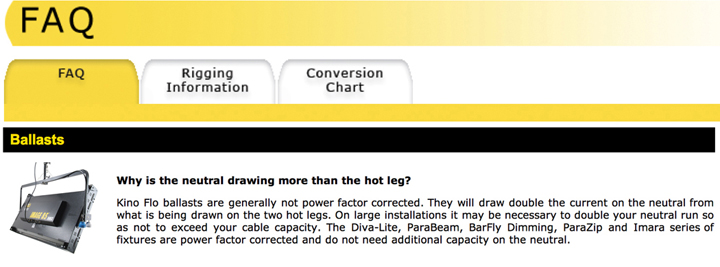
For this reason, on their website Kino Flo cautions that "On large installations it may be necessary to double your neutral run so as not to exceed your cable capacity." What effect can such high neutral returns have on an individual 400A 3-Phase company switch powering a number of Image 85s? If we take the rig pictured below for example, we see that there is the potential to severely overload the neutral bus of an individual company switch if precautions are not taken.
The 180 lamp heads pictured in this rig would require a service of 1’407A or 469A/leg on a 3-phase service. And since these ballasted lamp heads should not be operated on a dimmed channel, rigging crews will patch them into company
switches in the elevated catwalks rather than bring power for these heads from a central dimmer room. For this reason, company switches in the perms will be loaded to capacity before the rigging crews bring power up from below.
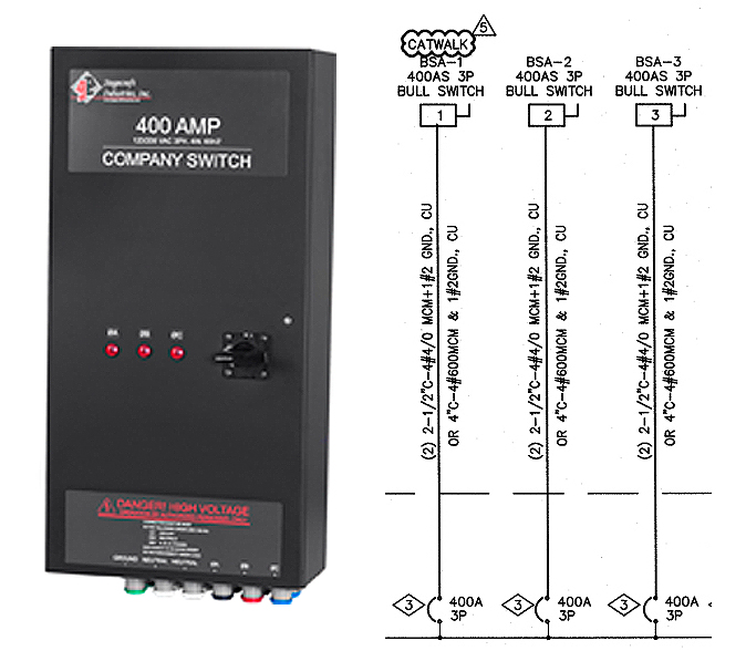
Typically a rigging crew will not load distribution equipment beyond 80% of its' rated load. Which means that in this situation, they will load each phase leg of a 400A/3-phase company switch in the perm to 320A before bringing more power up from a company switch below. If each phase leg is loaded as such, according to the results of our test we can expect a return on the neutral of 563A (320A x 1.76 = 563.20A.) Since the neutral return of a distribution system has no over current protection, return currents of this magnitude can cause sufficient heat to overload the neutral wire, and the neutral bus of switchboards, unless special precautions are taken.
Purpose built to accommodate the high preponderance of non-linear lighting instruments – HMIs, LEDs, as well as Fluorescents - used in motion picture productions, the system neutrals of motion picture stages are oversized. But,
where it is not possible to build a stage that can accommodate every conceivable type of production that could take place in it, and since the 176% returns of effects shows using Image 85s by the hundreds is outside the norm,
the electrical distribution systems of motion picture stages are typically designed to carry neutral currents that are no more than 120% of the current that can be carried on an individual phase leg. Since, neutrals oversized by
a factor of 1.2 are not sufficient for effects shows using Image 85s by the hundreds; Rigging Gaffers must therefore develop a means for accommodating the extremely high neutral currents generated by Image 85 fixtures.
Overheating and the pre-mature failure of Service Transformers:
The effect of using a large number of non-linear loads, like Image 85s, on facility service transformers have been well documented in recent years. Not only do triplen harmonics add to create unusually high current levels in the
neutral, but the heat they generate also significantly increases core loss in transformers. For this reason, motion picture stages use special transformers, called K-rated transformers, that are designed to withstand the extra
heat produced by normal loading with non-linear lighting loads. A typical studio service transformer will have a K-rating of 20 which means that it has sufficient core steel, neutral connections, and neutral wire size to carry 120% of the phase current for which it is rated.
Though purpose built to accommodate the high preponderance of non-linear lighting instruments used in motion picture productions, the service transformers of stages are not equipped to handle the unusually high return currents
generated by hundreds of Image 85 fixtures. This is another reason why Rigging Gaffers must develop a means for accommodating the extremely high neutral currents generated by Image 85 fixtures.
Voltage Distortion :
In addition to high neutral currents and transformer loss, there are other, less well documented, but potentially more serious problems associated with harmonic rich loads like the Image 85 fixtures. They include the heavy voltage distortion and high
neutral-ground voltages (common mode noise) that are common where high densities of non-linear loads exist.
Voltage waveform distortion is the result of the interaction of the harmonic currents with the impedance of the electrical distribution system. That is, as the harmonic currents circulate through the electrical distribution, they produce voltage drops at
each harmonic frequency in relation to Ohm's law - Vh = Ih x Zh. The combined effect of the voltage drops at each harmonic frequency creates a form of voltage waveform distortion referred to as “Flat Topping.”
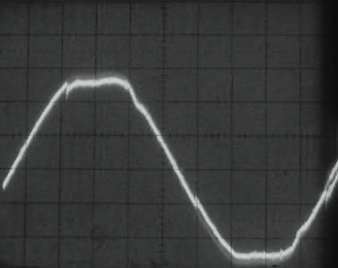
Where there is appreciable voltage flat topping, other electrical devices operating on the same power are unable to use the distorted waveform effectively. For instance, other production equipment that utilizes diode-capacitors and therefore depend on the peak value of the voltage waveform to operate effectively will work sporadically, if at all, on the squared off waveform caused by harmonic currents (above). 
Effect of DC Bus Voltage with Flat Topping
Special precautions must be taken with computers and hard drives. The majority of computer based equipment derives its’ internal DC power from AC power switched by a SMPS, or similar power supply, and so it is often here where harmonic problems first arise. As is evident in the illustration above, voltage flat topping from harmonic currents reduces the operating DC bus voltage these power supplies will generate. As a result, the load will be starved of power even though you may read full line voltage with an RMS meter and the power indicator lights light.
Neutral-to-Ground Voltage:
The same Ohm's Law relationship that results in voltage waveform distortion also creates high neutral-to-ground common mode noise voltages. Heavy neutral currents, resulting from the additive effect of the triplen harmonic currents (discussed above) in
the neutral will produce a voltage drop along the neutral conductor if not adequately sized. This voltage drop will appear as a potential difference between neutral and ground near the harmonic generating loads (ie. at the company switches and distro box
receptacles). Commonly referred to as common mode noise, this voltage can have an adverse affect on the operation of equipment which is subjected to it. This is another reason why Rigging Gaffers need to devise a strategy to mitigate the adverse effects
of harmonic currents in the stage distribution system.
Ground Currents:
Current on neutral conductors with a high THD value will induce voltage in ground wires greater than the 2 volt maximum stipulated by IEEE Standard 1100-1992 "Recommended Practice for Powering and Grounding Sensitive Electronic Equipment." This phenomena, called Proximity Effect, increases significantly in the presence of harmonic currents and can lead to the formation of “ground loops.”
A ground loop occurs when there is more than one ground connection path between two pieces of equipment. The duplicate ground paths form the
equivalent of a loop antenna that very efficiently picks up interference currents. Lead resistance transforms these currents into voltage fluctuations. As a consequence of
ground loop induced voltages, the ground reference in the system is no longer a stable potential (a floating ground), so signals ride on the noise. The noise becomes part
of the program signal. The result is that the unwanted signal will be amplified until it is audible and clearly undesirable. Whenever you have current induced on the
grounding system as well as the multiple connections between electronic components that is typical of HD production packages, there is the potential for a "ground loop."
PHOTO COURTESY OF THOMI ENGDAHL

Interference bars caused by induced voltage on ground loop.
Small voltage differences just cause noise to be added to the signals. This can cause an audio hum, interference bars to video signals (above), and transmission errors
in computer networks. Higher currents can cause more serious problems that can damage equipment like sparking in connections and burned wiring. As more and more electronic
components, like lap top computers, hard drives, and HD monitors, are integrated into the typical location HD production package, ground loops become more of a hazard.
Like most electronic equipment which utilize switch-mode power supplies around audio systems, Image 85 fixtures are equipped with filters to reduce their high frequency EMI emissions. While these filters are effective at reducing EMI, they allow
low frequency harmonic leakage currents (ie. 180 Hz) to pass through to the ground wire. This can result in troublesome ground currents circulating through the power system and need to be addressed as well.
High Inrush Currents:
As can be seen in the Power Quality Meter reading of a single Image 85 fixture below, Image 85 fixtures exhibit a high inrush current (70A) when struck cold.
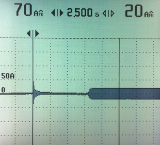
The reason the inrush current is 830% of the steady-state rms current of 8.4A is that the electronic ballasts of Image 85 fixtures use large smoothing capacitors to convert rectified AC to DC before switching to a high frequency output (greater than 25kw Hz.)
If we scale up this characteristic of Image 85 fixtures to the potential load placed on a company switch by a special effects show, we see there is a potential inrush current on an individual company switch of 2’660A on each phase leg (320A/8.4A per fixture = 38
fixtures per phase leg)(38 fixtures x 70A Inrush Current per fixture = 2660A Inrush Current per phase.) Inrush currents of this magnitude can result in nuisance tripping of switch board breakers and so must be addressed as well.
Conclusion:
What means are available to Rigging Gaffers to mitigate the adverse effects of Image 85 fixtures described above? The options include, in this case, the de-rating of service equipment, the use of supplemental power generated by diesel generators and distributed through purpose built systems with double neutral capacity, or the use of Harmonic Mitigating Transformers to prevent triplen harmonics from reaching a stage’s hardwired distribution system. Where each of these “solutions” have a downside, the merits of each must be weighed on a case by case basis. What is certain, however, is that given the nature of lighting instruments today, to safely distribute electricity on large stage rigs, electricians need to understand the origin of harmonic currents, their effect on equipment Power Factor, how they interact with a system’s impedance, and the inherent limitations of a stage’s service equipment in handling them. An awareness of these effects is the first step towards developing successful strategies for eliminating or mitigating the adverse effects of harmonic currents.
|